Monday, August 26, 2013

End of Summer Break Massive Update

So it's that time of year again where I have to put most of my projects on hold until I come back home for a break. It's a bittersweet time but I wanted to give a quick update on my current projects that I've made headway on but unfortunately will not get to complete for awhile. I can't be bothered to do individual posts because I'm busy packing but here is everything I have been working on this summer in a huge picture and video filled montage.

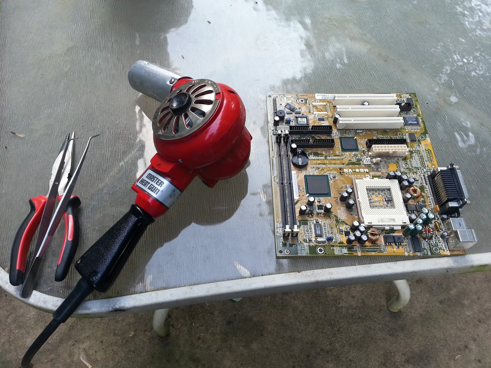
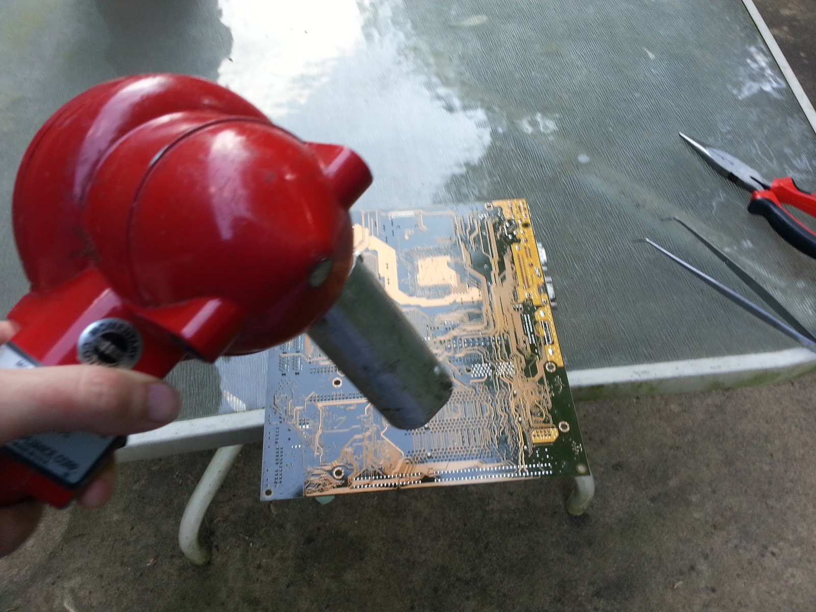
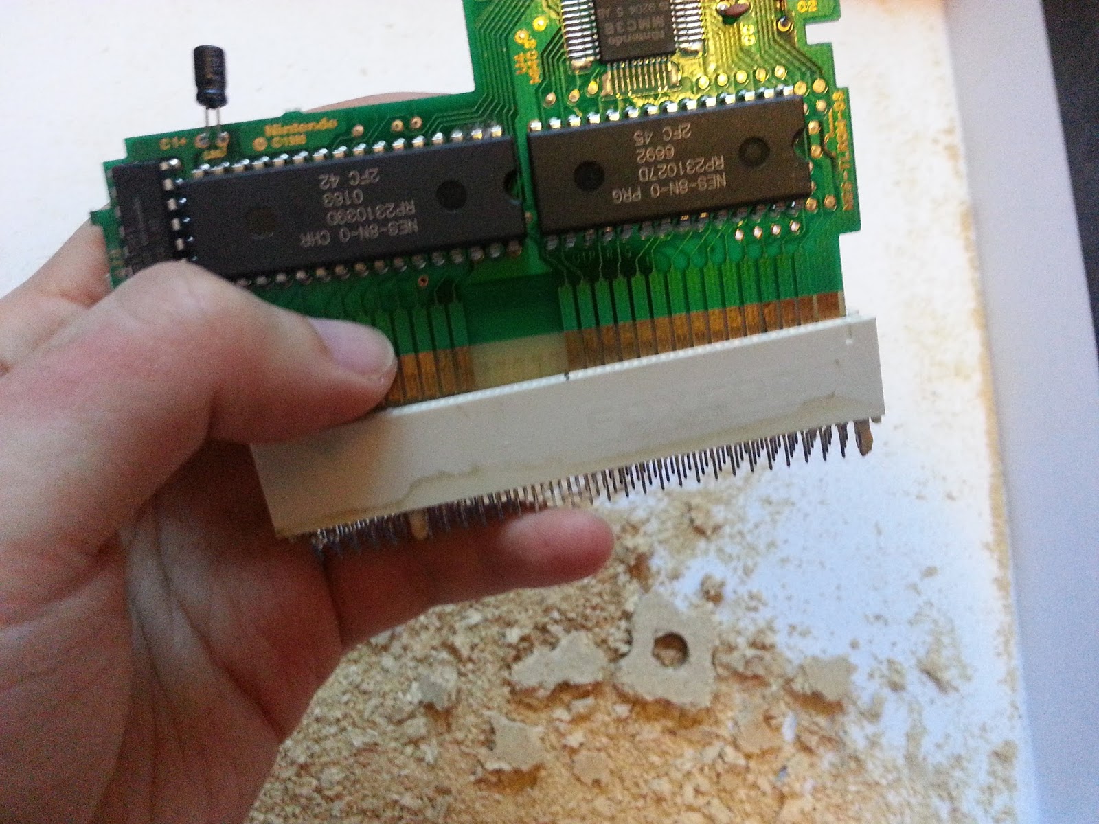
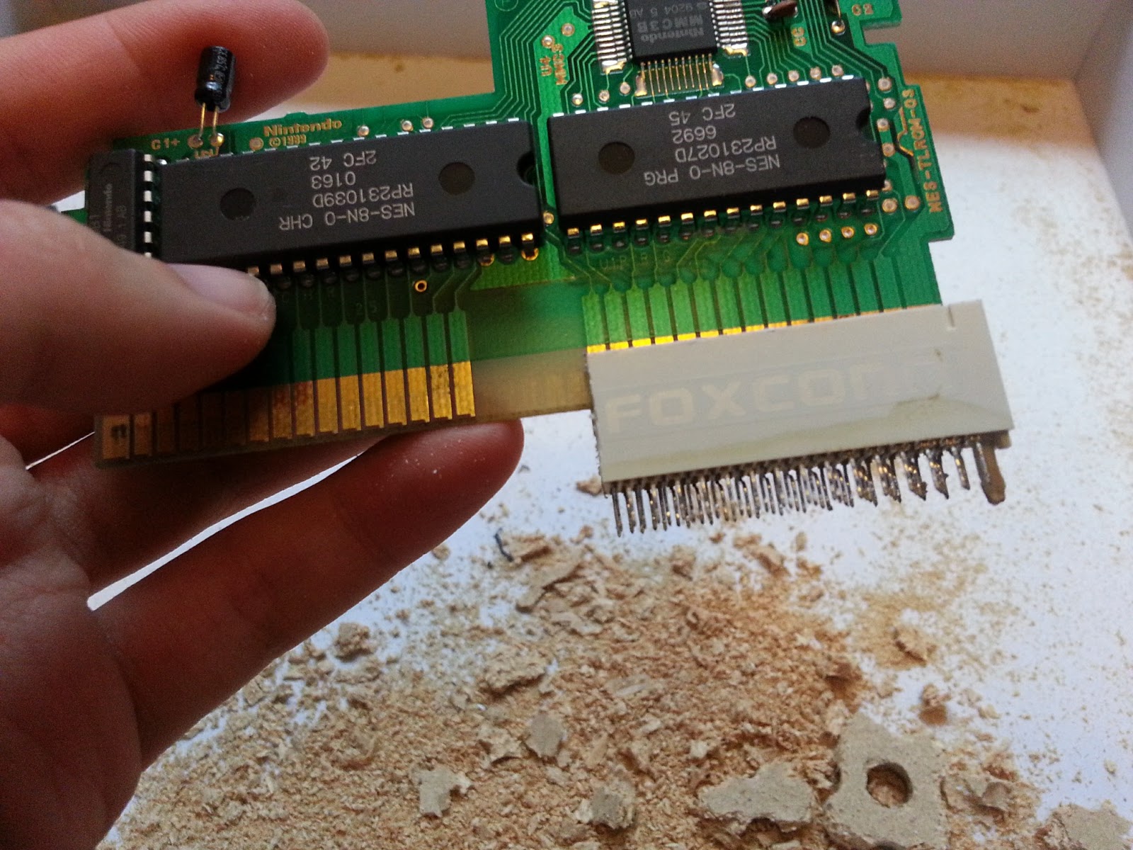
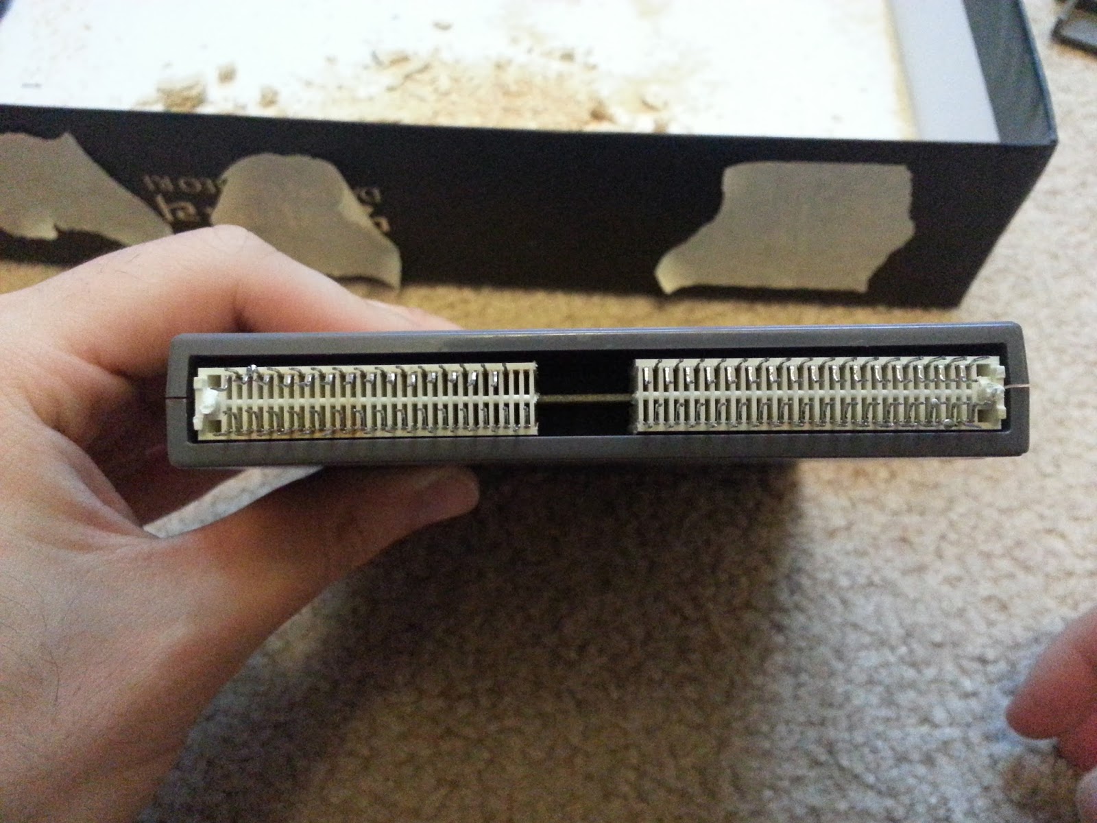
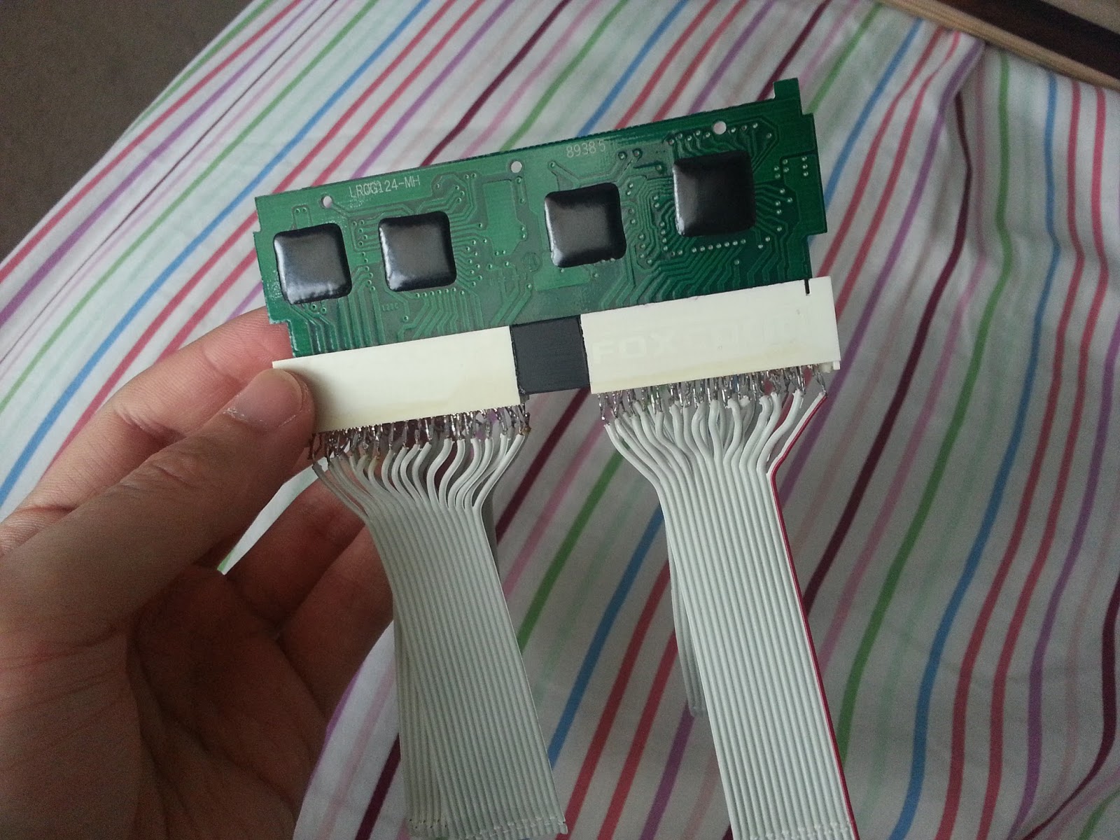
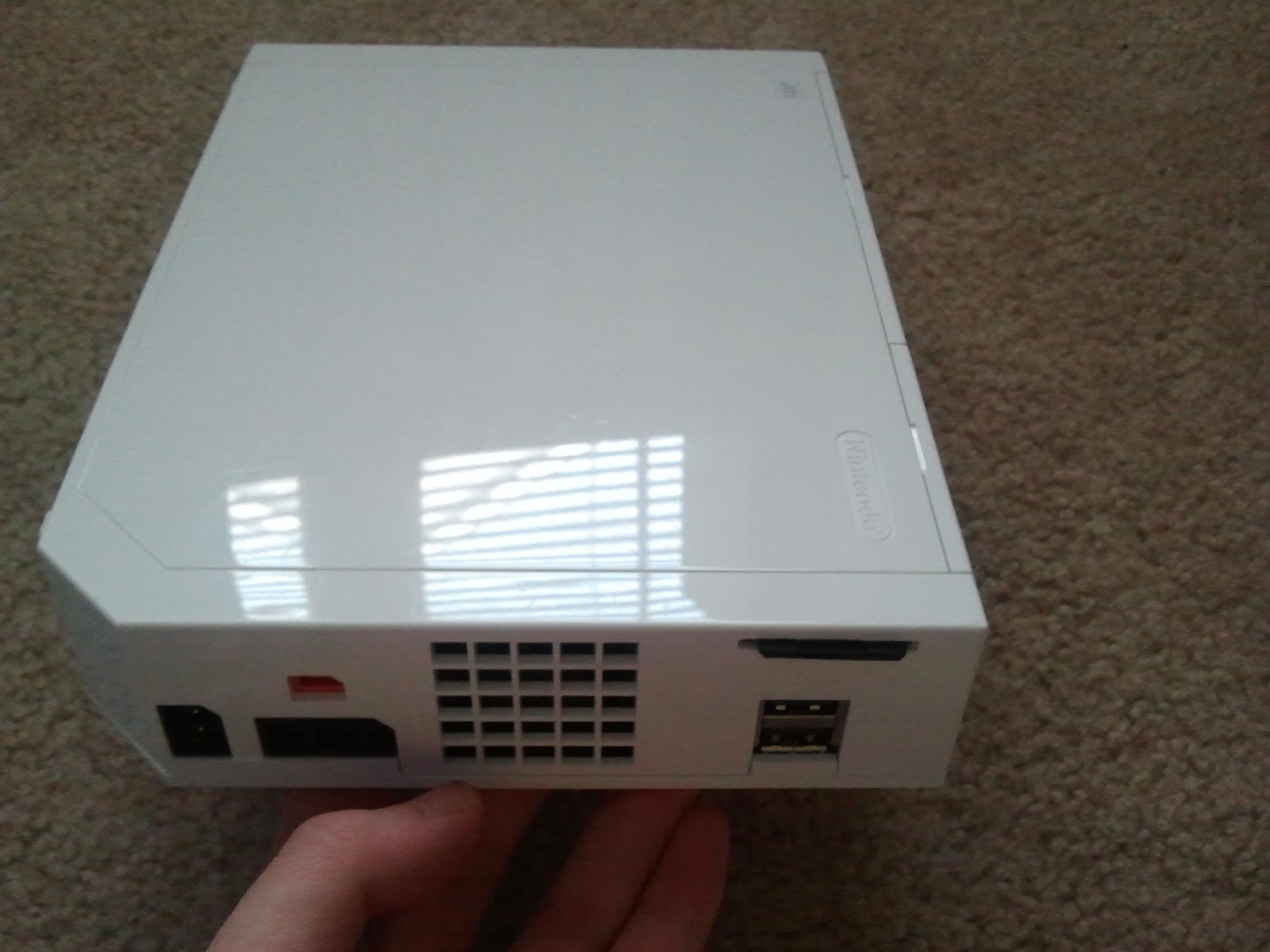
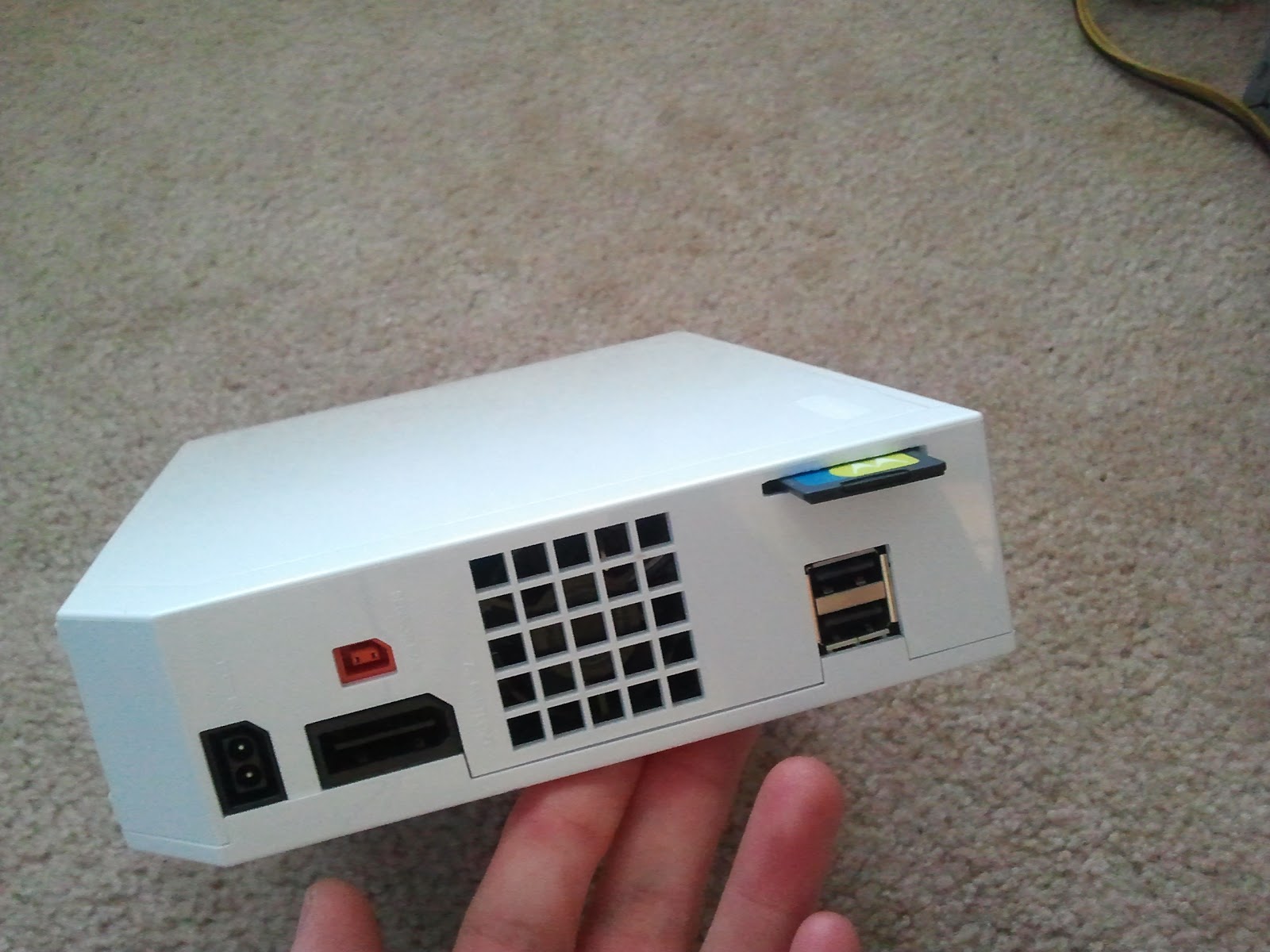
First up is my portable SNES project (it will end up barely being larger than a game cart). This starts with a short story so here it is. I found a "broken" retro duo at a used game store for $4 so I couldn't say no (I even made a short video on it up on my youtube account - sjm4306). I took it home and immediately tested it to find that the SNES side was still fully operational but the NES side was kaput. Ok this worked for me because I ordered a free sample of a small enclosure from OKW awhile ago that is almost the exact size of a SNES cart so I've been wanting to make a tiny portable SNES. So I set out to trim the retro duo SNES board to fit in said enclosure. Here are some progress videos.

Progress Video #1
 
Progress Video #2
 Progress Video #3
Progress Video #4


And that is where I left off. I need to find a cheap 3.5" composite lcd off of ebay which will work. The majority that I bought in the past seem to have rolling video issues with the video output of clone systems. So I will try and see if I can find one that works while I am at college. I plan on finishing this guy up over winter break after I come home.

And now for something a little different. The second project I've been working on is a 3V DC to 200V AC inverter so I can drive an electroluminescent (EL) panel to backlight an old gameboy pocket I have laying around.


Did I ever mention I love clear or translucent electronic devices ... anyway back to the update. I carefully removed only the back reflective layer on the lcd so I could backlight it. For the electronics I used a pic16f886 (I will end up porting the code to a smaller pic later after I get everything working) to drive an inductor based inverter. This generates around 200V DC which I then chop up to simulate AC with another output from my mcu. I will make a simple schematic and place it below when I get the time but for now here are some pics of it driving various EL panels I pulled from old electronics.


For fun I wired a voltage doubler to boost the output to 400V AC. It all works off of a 3.7V lithium ion battery and only draws about 25mA.
And that is where I left off. I still need to move on past the prototyping stage. I'll finish it later.

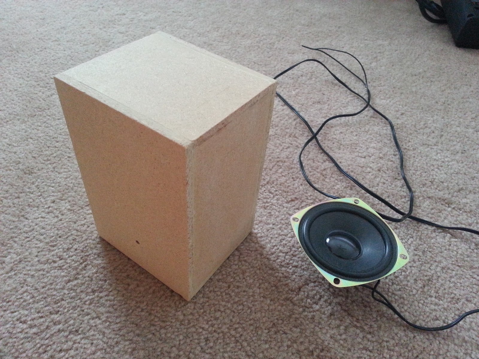
Next up I finally got major work done on my desktop speakers and class D amplifier. I pulled the speakers from a system someone threw out and the wood came from an old speaker cabinet with a dead subwoofer. I cut everything with a hacksaw and finished it with sanding blocks and my dremel.
I can be very methodical and organized when I try. Warning crap loads of pictures below.


And here is the TI TPA3122D2 stereo 10W class D amplifier to drive the show. I did a short test video.

I bought some sealant and spray paint for the enclosures which I still need to finish. I just need to mount the amp (I'm tempted to go with a digital volume and control system with a rotary knob and lcd screen) and then I will be done this entire project.

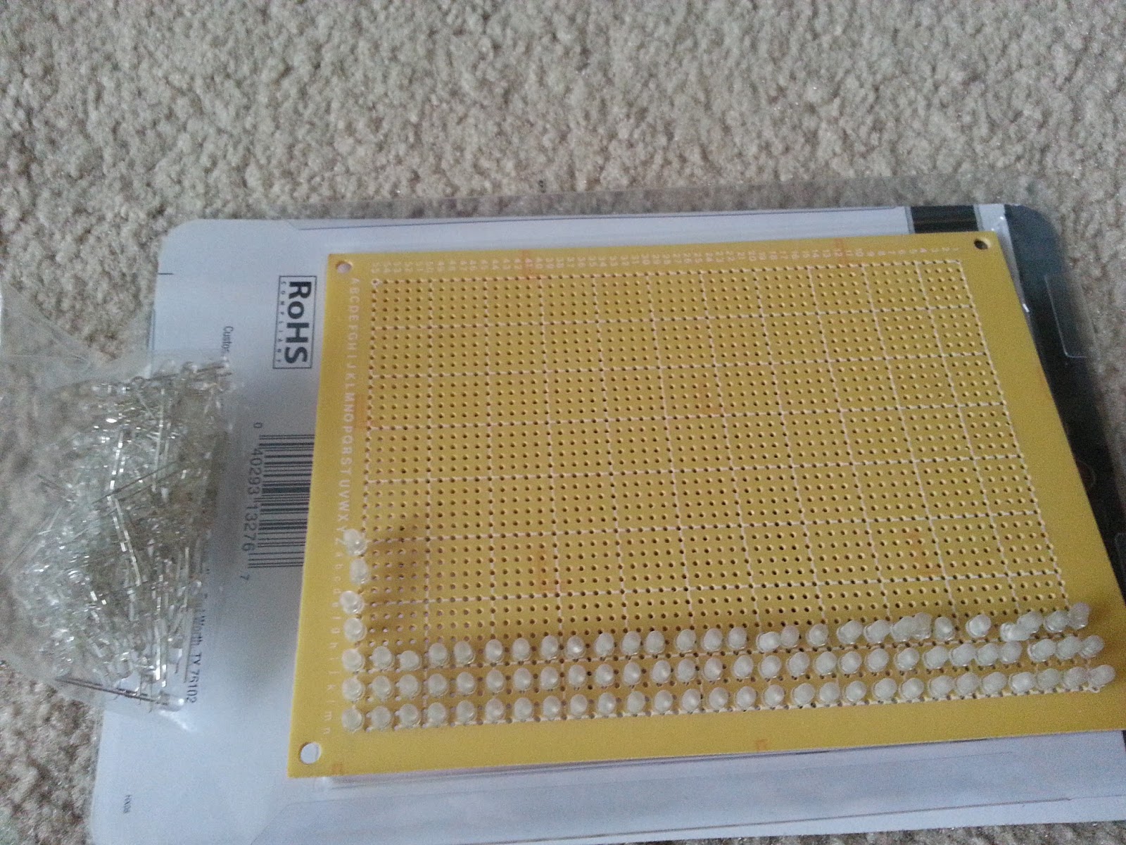
Finally my last project was to build a clock. But it won't be just any clock. I bought a bag of 200 water clear blue leds off ebay that I've been itching to use. 
So why not make a huge led matrix and make a clock that can also scroll text from a computer. The only problem is how to diffuse 200 leds by sanding each and every one.
Before
After
My solution:
1000 grit sandpaper and an electric drill.

Unfortunately I only got around to sanding half of the leds before I got sick of it so this project is on hold. I even got as far as trying out wood for the front panel.
But I opted for just mounting the leds on perfboard for ease of assembly.

I still have to finish sanding the rest and solder (oh what fun) all the leads to the board. Oh well I'll leave all that till I have enough motivation to finish this.

Finally (the truth this time) I would like to end off with a perler bead creation I made. I found some old beads my sister and I played with when we were kids so I found it fitting to make some video game sprite art to hang on my wall. Say hello to Samus from the original Metroid.

But it all ended quickly as I only had enough for one sprite. Oh well, maybe I'll pick up some more beads later so I can make an entire montage to tape to my wall.

And that is about everything I have done this summer (aside from work and taking graduate record exams). Phew that was exhausting. Before I finish I also want to let you guys know that I wont be making posts for TeardownTube episodes on my blog so if you want to see new episodes then subscribe to my Youtube channl sjm4306. With that out of the way I hope you enjoyed my adventures. Although summer is drawing to a close I have much planned for both my blog and Youtube so stay connected.

Thursday, July 11, 2013

Super Joy 3 NES on a Chip Modifications

As a preface to the ongoing project below, as usual I was wandering Ebay and I happened upon a used Super Joy 3 for $8 so I couldn't say no. It is a "Famiclone" or also known as a NOAC (Nintendo on a Chip) meaning it is a cheap Chinese reverse engineered custom ASIC of the original NES. The beautiful thing is that is has a onboard Famicom 60 pin slot to accept original games. This can be rewired to accept US NTSC 72 pin NES games. So I set about making these modifications in order to build my own tiny portable NES. The only thing that stands between me and my dream is that I lack a 72 pin NES cartridge connector and I dont want to buy one if I can help it. So how did I work around this problem? Ingenuity!

I simply took an old ATA PC motherboard and desoldered the PCI connector slots from it with the help of my handy heat gun (warning it may look like a hair dryer but it gets MUCH hotter!) as I noticed it was about the right fit for the NES cart edge connector.

One problem is that the 72 pin card is much too wide so I needed to cut and splice two sockets together. Here I marked off where to cut by opening up a NES cart for reference and used a small hacksaw.


Looked like a good fit. But the PCI slot has many more pins than necessary and the alignment was a little off so some had to be removed with pliers to insure there were no shorts.
Both sides were now finished so I set about finding the right fit and tediously testing each pin with my multimeter. Overall everything fits like a glove.

Now I needed to add some plastic spacers to connect both sides and give some mechanical rigidity
 so I added some scrap black ABS plastic cut to size with my Dremel and glued with some super glue.
Finally I soldered the 60 some pins with IDE ribbon cable and rechecked the connections with my multimeter. Notice how the center five pins which would be located at the black plastic are not connected on either side. This is because these were brought out to the bottom expansion port of the NES which was never used to I left these pins out.
This is where I left off for now. I still need to remove the Famicom cart slot from the Super Joy 3's PCB and solder in my FrankenCart Slot. I'm keeping my fingers crossed that everything works. If not then this was still a good exercise in modifications. I'll update this page when I make more progress.

Wednesday, May 22, 2013

Update and Quick Wii Mod

Its been awhile since I posted my last project but now that I'm done with classes and finals I can get back to working of some unfinished and new projects. I've got plans involving retro game systems, toasters, lasers, motors, mirrors, hard drives, lcd screens, microcontrollers, and much more. It'll be a summer of hacking and making and I will enjoy every moment of it. So I hope you will too as I strive to bring more documentation and worklog videos to my site and youtube channel.

With that out of the way I decided to start off my summer by finishing a project that I've been putting off for quite awhile. A few years ago I found a $30 Wii at a thrift store that was in perfect operational condition. I instantly purchased it and went home to see about modding it. I was fortunate that it was a launch model which meant that the drive could read recordable discs unlike the newer D4 drives which could not. So I went and bought a Wiikey Fusion for around $40 and installed it in between the original drive and the motherboard. This device would allow me not only to play my backup games, but also play games off of an additional SDHC card.
From my understanding, the device works by patching the security code into the data bus when playing a copied game, or by emulating the original disc drive when play off of the SD card. Because it is a hardware Actel FPGA implementation, Nintendo can do very little in the way of software updates to restrict its use. The installation was very simple. I had to remove the internal disc drive, place the fusion in between the Wii's mainboard and drive, and attach the SD card reader to the fusion. This took minutes and only required a tri-wing and small phillips screw driver and a small pocket knife (instruction can be found online). I then fed the SD card wiring to the outside and mounted the slot on the outside. It stayed this way for the good part of a year.

Just yesterday I wanted to play some Skyward Sword and found the externally mounted card an annoyance and hideous to be honest. So I decided to internalize it last night and did the modifications this morning. The fruits of my efforts can be seen below.

The problem is that there is very little free space in the Wii where I could mount a SD slot. I wanted to leave the front facing slot untouched so I opted to mount the second slot on the back above the two USB ports. For this I need to move the Wifi antenna down a bit and tape it to the top of the air duct plastic. Then I used a dremel's drum sander to remove the plastic mounting standoffs from just above the two gamecube memory card slots right under where the SD card is mounted. This allowed me to mount the small board flat so it would fit in the small space. I then used hot glue to hold the slot in place.
Next I used my dremel with the cutoff attachment to cut a rough SD sized slot after doing some measurements and drawing the outline on the plastic with a pencil. I then finished the cut with a pocket knife to clean up the edges. I made sure everything lined up and found that the screw post just to the right of the slot was preventing the case from closing. I took off a bit of the plastic and then everything fit like a glove.


In the end the slot is still a little rough but it can be cleaned up later. But for now I have a hard modded Wii with an internal secondary SD card slot to play backups off of. Everything looks stock with the exception of the small slit on the back. I am very happy with how this turned out and now I need to get back to playing some LoZ :-)